With the advent of low-cost aerial platforms like UAVs customers are increasingly becoming interested in capturing their own aerial imagery for use with 3DM Analyst.
Aerial photography is most attractive in applications where the view from above allows areas to be seen that are not visible from the ground — such as the inverted cone in the top of this stockpile:
In this post I’ll cover the issues to be aware of based on my own experience with aerial photographs captured both from UAVs and from conventional aircraft.
Camera Orientation
The first issue is the camera’s orientation. For aerial projects we normally need to do multiple strips of parallel images so we can cover a large area:
The most efficient way to do this (in terms of minimising the wasted pixels) is to orient the camera vertically so it’s looking straight down at the ground. (Oblique images can be used instead if necessary — to capture the face of a pit wall, for example — but it’s harder to capture and process multiple strips of images if the images are oblique.)
But what should the rotation of the camera be with respect to the flight direction?
If you’re using a high-end camera with forward motion compensation then it must be oriented in the direction that the FMC mechanism operates in. Most of those cameras have square sensors anyway, so it doesn’t really matter.
But the digital cameras that most of us use have non-square sensors, so the orientation of the camera does make a difference.
Consider a Canon EOS 5D Mark II with a 24 mm lens, for example. At an altitude of 120 m/400 ft it has a footprint on the ground of 180 m × 120 m. If we orient it such that the flight direction is to the top of the camera (in other words, the camera sees the ground moving down with respect to it) and use the normal 60% overlap then the geometry of the first two images would be as follows:

(Blue represents the first image, yellow the second, and green the area of overlap.)
The model area is 72 m × 180 m, so to capture an area of 1,000 m × 1,000 m with a 20% overlap between strips we would need a total of 147 images arranged in seven strips of 21 images per strip. The base:height ratio is 1:2.50, and with an image accuracy of 0.5 pixels the expected planimetric accuracy would be 1.6 cm and the expected height accuracy would be 4.0 cm.
Now suppose we rotated the camera 90 degrees, so that the long axis of the camera was in the flight direction (and the camera therefore sees the ground moving sideways with respect to it):

Now the model area is 108 m × 120 m, so to capture an area of 1,000 m × 1,000 m with a 20% overlap between strips we would need a total of 154 images arranged in eleven strips of 14 images per strip. The base:height ratio is 1:1.67, and with an image accuracy of 0.5 pixels the expected planimetric accuracy would still be 1.6 cm (because the ground pixel size hasn’t changed) but the expected height accuracy has improved to 2.7 cm.
Normally aerial projects are planned based on a desired height accuracy, because this will always be the least accurate co-ordinate. In the first case the height accuracy was 4 cm. In the second case the height accuracy improved due to the base:height ratio change, but the number of images increased slightly. What if we took advantage of the improved height accuracy to fly higher?
A quick calculation shows that we would achieve exactly the same height accuracy as the first example if we flew at an altitude of 180 m. In this case we would only need 63 images arranged in seven strips of nine images per strip. The planimetric accuracy would be 2.4 cm while the height accuracy, as suggested, would be 4.0 cm. The project is less than half the size and the limiting accuracy — the height accuracy — is exactly the same!
For this reason we normally use the second camera orientation. To achieve the same height accuracy with the first orientation requires you to fly lower, capturing more images and creating more work for yourself.
Even worse, the first option is more sensitive to any bumps or timing errors that you might have because the tolerances are tighter.
The big downside to the second option is that more strips need to be flown and the distance between the strips is less. The more relaxed tolerances along the flight path are traded off for tighter tolerances between strips. For a UAV this isn’t a big deal because flying time is very cheap and staying within 10 m of a flight line isn’t a problem, but if you’re using a conventional aircraft flown by a pilot, the extra flight time and the difficulty in flying parallel, nearby strips can be a problem.
A height accuracy of 0.1 m is a very common specification for surveying. With the Canon EOS 5D Mark II and 24 mm lens using the first option this is achieved at a flying height of 300 m (1,200 ft) and a 2 km × 2 km area would need six strips of 17 images each for a total of 102 images. With the second option it is achieved at a flying height of 450 m and a 2 km × 2 km area would need six strips of seven images each for a total of 42 images.
Lens
In the above examples I’ve used a 24 mm lens throughout. The reason for this is geometry: with strip photography, the base:height ratio is determined by the focal length of the lens and the desired image overlap. In the image below, you can see that with a flying height of 120 m, the camera separation must be 72 m in order to maintain the 60% image overlap (108 m/180 m):

This means the base:height ratio is 72:120 = 1:1.67, which means the height accuracy will only be 1.67 times worse than the planimetric accuracy.
Longer focal length lenses necessarily require camera stations to be closer together at the same flying height in order for the image overlap to be the same because the image footprint on the ground is smaller. If the flying height is increased to the point where the image footprint is the same as the shorter focal length lens, the camera separation will also be the same. So, with the same camera and image overlap as before but with a 50 mm lens, we get the following geometry:

Now we’re flying at 250 m in order to get the same ground coverage and same overlap, but our base:height ratio is 72:250 = 1:3.47, which means our height accuracy will be 3.47 times worse than our planimetric accuracy.
In both of the examples above, the planimetric accuracy will be the same because the ground pixel size is the same, but the height accuracy will be twice as bad in the second case. Since height accuracy is normally what is specified, it makes sense to prefer the shorter focal length lens. It’s also more resilient to bumpiness during flight because a small change in angle of the camera will have less impact on the overlap than it would with a longer focal length lens.
Conversely, if the original flying height of 120 m was maintained, then the height accuracy would be the same, but the planimetric accuracy would double and, in a multi-strip situation, over four times as many images would be required!
The limit on how short the focal length can be is really lens quality. We use the EF 24mm f/1.4L II USM lens, which is very expensive but has very good image quality. We also have the cheaper version (EF 24mm f/2.8) and its blurriness towards the edges of the image requires an aperture of about f/11 to eliminate, making it difficult to get a reasonable shutter speed. The 20 mm lens is even worse.
Camera Setup
Normally we advise customers to use the following image settings:
-
Aperture Priority mode
-
Aperture: f/8
-
ISO: 100
Aperture priority mode allows the camera to automatically determine the shutter speed to obtain a correctly-exposed image while the aperture and ISO settings are held fixed.
This works well provided the shutter speed doesn’t matter, and for normal terrestrial photography it usually doesn’t. (For long focal length lenses it’s a good idea to use a tripod and a remote shutter release to avoid motion blur.)
With aerial photography the movement of the camera during the image exposure places severe contraints on how slow the shutter speed can be. For the 5D Mark II with 24 mm lens at 120 m, for example, one pixel on the ground is 3.2 cm and if the camera is moving at 5 m/s (e.g. a UAV) then the camera will move 1 cm during a 1/500 second exposure. In a conventional helicopter travelling at 80 kts it will move 8 cm during a 1/500 second exposure. Shutter speed is therefore very important and should be chosen to ensure that at the intended flying speed the camera does not move more than one-half or, better, one-third of a pixel during the exposure.
This, then, poses a problem: we need to ensure a reasonable shutter speed to avoid motion blur, but at the same time we want the camera to be able to adapt to changing light levels during a flight (because, for example, clouds might be passing overhead, or there might be a wide range of albedos in the terrain being flown).
My personal preference is to continue using aperture priority mode (so the camera can adjust shutter speed as required) but then choose an aperture and ISO combination that ensures the shutter speed is high enough even with the darkest terrain likely to be seen. To do this I look for dark terrain in the vicinity, point the camera at it, and then press the shutter half-way down to see what the camera says the shutter speed would be. If it’s not high enough, I adjust ISO and/or aperture until the shutter speed is acceptable.
For example, with our UAV, I normally fly at 5 m/s and 120 m altitude and like to keep the shutter speed above 1/500 seconds. This is generally not possible with the settings given above. The first thing I change is the ISO, from 100 to 200, because I’ve tested the 5D Mark II and the level of noise this introduces into the images is minimal. A good example of such an image can be downloaded from our website. That particular image was captured by the UAV with the aperture set to f/8 and the ISO set to 200 and the shutter speed the camera used was 1/1250 seconds, well above my desired threshold.
If it’s still not fast enough — either because the ground is particularly dark, or the ambient lighting is low — then follow the sequence below:
-
If it is still slower than 1/500, increase ISO to 320.
-
If it is still slower than 1/500, change aperture to f/7.1.
-
If it is still slower than 1/500, change ISO to 400.
-
If it is still slower than 1/500, change aperture to f/5.6. By this time the terrain must be really dark or the light levels really low! Consider scheduling the flights for between 10 am and 2 pm to maximise light levels if you can.
Even with the good 24 mm lens mentioned above the final step will introduce some softness in the corners but won’t affect the results too much.
One more tip: I’ve found that the default exposure settings on the camera are often a little bright, and can wash out the image in some areas excessively. Adjusting the Exposure Compensation down 1/3 or 1/2 a stop will darken the overall image, making it less likely that a bright area will be overexposed, and also increasing the shutter speed. (Another option is to shoot in RAW mode rather than JPEG, because RAW images usually have 2–4 times as much dynamic range as JPEG images, but I prefer the convenience of JPEG.)
Focussing
Focus is obviously really important, and even more so with aerial photography because the effort required to capture the images is higher than normal. Never forget to ensure that the focus is correct before the flight!
I use the following procedure:
-
Switch the lens focussing control to MF (manual focus).
-
Switch to “Live Preview” mode by pressing the button to the left of the viewfinder.
-
Press the zoom-in button on the right (magnifying glass with + symbol) twice to zoom in 10X on the live preview.
-
Rotate the manual focus ring until the image is sharp. Focus on an object that is distant, at least 10 metres, preferably 20+ metres.
-
Tape the focal ring, being careful not to rotate it, to prevent it from being adjusted again. Also tape the AF/MF switch to prevent that changing. We use vinyl plastic electrical tape.
-
Take a photograph, then zoom into the image to check that the focus is exactly right. Ideally copy the photograph to a laptop and zoom in, otherwise zoom in using the display screen on the back of the camera. (On Canon cameras this is done using the Magnify button to zoom in, and multi-controller to pan the zoomed area.)
Use a tripod when photographing to ensure that camera movement doesn’t cause blur. It’s a good idea to find a very thin object in the scene to use for checking the focus. I use some power lines across the street from our office because they’re only about one pixel wide and if they are out-of-focus it is very obvious.
Note that even after all this effort to fix the focus, it is still possible for it to change, unfortunately — the modern lenses don’t prevent the focus from drifting even in manual mode and even with the focus ring taped. It’s a good idea to double-check the focus in the field just before the flight using the above procedure. Even in manual focus mode the camera should beep and flash the little red boxes in the viewfinder if the shutter is pressed halfway down when looking at some distant objects and the camera is in focus.
Redundancy
In the above discussion I’ve assumed an image overlap of 60%, and, indeed, that’s what we normally use when processing pairs of images. However, since actually capturing images doesn’t cost anything with a digital camera, it pays to capture images more often than that to provide some redundancy. Sometimes the aircraft flies through or above a cloud at exactly the wrong time, or experiences a particularly nasty bump or a cross-wind gust just as it’s capturing the image, making it blurry even with the carefully-chosen shutter speed. It’s nice to be able to throw the image away without having it affect the results.
For this reason I normally use an 80% overlap, capturing images exactly twice as often as needed for the 60% overlap case. (90% overlap would require capturing images twice as often again.) This allows every second image to be discarded without creating a hole in the DTM, and it requires three bad images in a row before the DTM is missing data. In cases with infrastructure obscuring the surface of interest, like conveyor belts over stockpiles, it also helps to see the entire surface beneath the infrastructure because of the many different vantage points.
Direction
What direction should you fly in? This depends a little bit on your aircraft.
If you are using a large aircraft and you can rotate the camera so that it is parallel to the flight direction even thought the aircraft itself is not (e.g. a plane flying in a cross-wind), then the flight plan can be made in advance to minimise the amount of flying required (e.g. plan the strips to be parallel to the long axis of the area being captured).
If you are using a UAV, consider orienting the strips so you are flying directly into and with the wind rather than at an angle to it. This may mean more flying and more images to process, but it also makes it easier for the aircraft to maintain heading and to stay on track.
With our UAV I normally decide which way I’m going to go onsite. I wrote a little program to generate flight plans on the fly given the area to be mapped and the desired flight direction. If prevailing winds are low enough I ignore them and just use the optimal flight path for the geometry of the area to be captured; if they are higher then I try to fly with them.
More Information
If you need any advice please don’t hesitate to contact us or ask a question below so everyone can see it!
#1 by Brent on 23rd February, 2012 - 7:00 am
Good article. Do you know of any software that will use the position and orientation of aerial images and plot the ground track and footprint? Preferably it would do it in batch mode, reading all files in a folder.
Thanks
#2 by Jason on 15th March, 2012 - 11:03 am
Hi Brent,
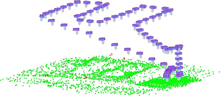
Sorry, not off the top of my head. In 3DM CalibCam you could load in the merged DTM and view the cameras in relation to it, like http://www.adamtech.com.au/FlightLines.jpg, but it doesn’t show you the image boundary on the ground itself.
Cheers,
Jason.
#3 by Jenna on 16th April, 2012 - 6:36 am
That was a great info. well discussed article and I’ve really learned a lot about it. I just only know basics camera shoot but with your article I learned about Aerial Photography. Thanks. 😀
Pingback: Aerial Mapping with UAVs and 3DM Analyst Mine Mapping Suite « ADAM Technology Team Blog