The 2.4 release of 3DM Analyst featured a number of enhancements to the DTM Filtering dialog box, accessible from the Build | Filter DTM Points… menu. In this post I’m going to explore how this dialog can be used to remove infrastructure from DTMs, like the conveyor belts visible in this colourised point cloud:

Filtering with a template
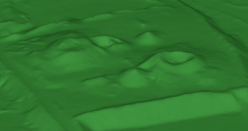
Suppose we had a DTM that represented a rough approximation to the surface and did not include any of the infrastructure:

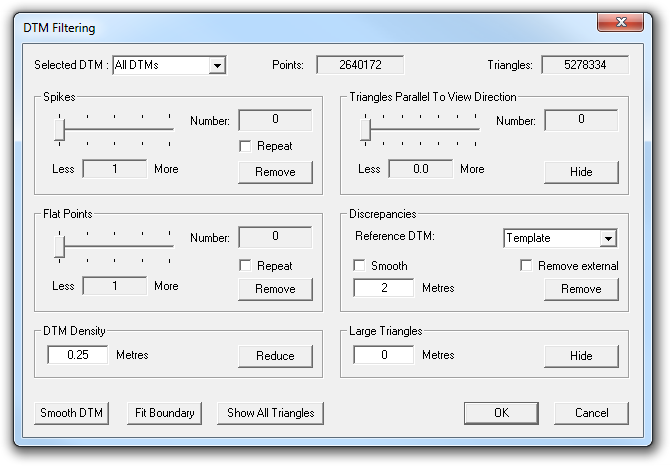
How could we use that? Well, the first step is to load in all of the DTMs plus this surface approximation DTM, and then bring up the DTM Filtering dialog:

Then we set “Selected DTM” to “All DTMs” and “Reference DTM” to the surface approximation DTM, named “Template” in this example.
Then we decide: what is the maximum vertical distance that the actual surface could be from our reference DTM? This is important because the next thing we are going to do is remove any point in any DTM that is greater than this distance away from the reference DTM. The ideal value to use is a distance that is greater than the largest possible distance from the actual surface to our reference DTM, but is also smaller than the smallest possible distance between the infrastructure and the reference DTM.
If we pick a value that’s too small, we may lose some of the terrain. If we pick a value too large, we may not remove some of the infrastrucutre. In this case I’ve decided to use a value of 2 m because I know my reference DTM follows the terrain pretty closely, and I also know that with aerial photography you tend to get points on the ground and points on top of the infrastructure (which is well above the ground — about 20 m in this case), but relatively few points on the infrastructure close to the ground simply because of the vantage point.
Then, making sure “Smooth” is unchecked, we click on “Remove”. (If “Remove external” is checked, it will also remove any points in any DTMs that lie outside of the footprint of the reference DTM. This is one way you can clip your DTMs to some pre-determined area, but it is not necessary for stockpile volume calculations because the volume calculation does that internally anyway.)
Once complete, the software will give a report on the number of points that were removed, the RMS difference between the points that were retained and the template, and the number of points that were removed because they were outside the reference DTM footprint (which will be 0 unless you checked “Removed external”).
Merging DTMs
One of the motives for removing infrastructure from DTMs is to calculate accurate stockpile volumes, and to do that, you need to actually merge the individual DTMs into a single DTM. Before merging, however, it’s worth visiting the DTM Filtering dialog again.
Whenever we create 3D data in the real world, there is always some error associated with that data. As explained in earlier posts on accuracy, we can predict the accuracy beforehand, but that accuracy is the accuracy of individual points in a single model. When we do a project with aerial strips, like we do with stockpile volumes, we can use many combinations of images to generate DTMs from many different vantage points, all with significant degrees of overlap. This is great for allowing us to see “underneath” infrastructure, but it also allows us to increase the accuracy of the data beyond what the simple calculations show, because now we have multiple samples of the same surface — a single point on the ground can easily be covered by five or more DTMs!
It makes sense to try to take advantage of these additional observations and increase the accuracy of the surface model, and the DTM Filtering dialog includes functionality for just that purpose.
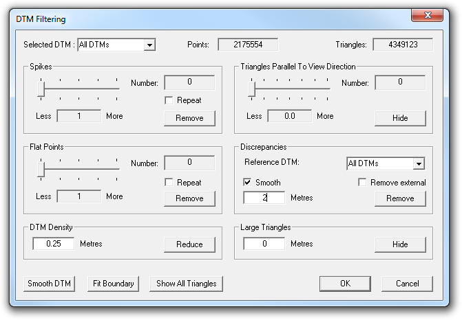
When we used it to check the DTMs against a template, we set “Selected DTMs” to “All DTMs” and “Reference DTM” to our template. To tell the software to use overlapping DTMs to improve accuracy instead, we set “Reference DTM” to “All DTMs” and check the “Smooth” checkbox:

What the software will now do for each point in each DTM is ask the other DTMs what they think that point’s height should be, and it will update that point’s height with the weighted average of all DTM’s opinions. (The weighting is simple — the current point height has a weight of 2, while each other DTM’s opinion carries a weight of 1. Thus, if the current height was 2.0 m, and one other DTM overlapped that point and said its height should be 1.5 m, then the new height would be (2 × 2.0 + 1 × 1.5) ÷ 3 = 1.83 m, representing a move 1/3 of the way from the original height to the height suggested by the other DTM. If, instead, there were two other DTMs and both said the height should be 1.5 m, the calculation would be (2 × 2.0 + 1 × 1.5 + 1 × 1.5) ÷ 4 = 1.75 m, a move of half-way. The original point has twice the weight of the others on the basis that it’s an actual matched point while the others are likely to be interpolated values.)
The distance figure has the same meaning as before, but with a twist — previously we assumed that the reference DTM was correct and if there was a point further from it than the specified distance, that point must be in error and was therefore deleted. Now we don’t know automatically which point should be deleted if another DTM gives a height that is more than the given distance away from the point under consideration.
So, what the software does for a given point is this:
If another DTM gives a height at that location that is more than the specified distance away from the point, the point is not marked as valid and the height supplied by that DTM is not used as part of the weighted average calculation.
If another DTM gives a height that is less than the specified distance away from the point, then the point is marked as valid and the height supplied by that DTM is used as part of the weighted average calculation.
If no other DTM gives a height for a point (i.e. they do not overlap) then it is marked as valid.
Points that are not marked as valid are then deleted, and points that are marked as valid have their heights adjusted. (The only way a point can be not marked as valid is if all overlapping DTMs gave heights that were greater than the specified distance away from the point.)
This allows DTMs to be reconciled and their surfaces to be moved towards each other iteratively without “bad” points (e.g. points on infrastructure) affecting them.
One other tip: if you hide a triangle, it won’t be used for reporting a height. The DTM Filtering dialog includes an option to hide triangles greater than a given size. Since a large triangle is less likely to accurately represent the surface within its extents, you can type in a size under “Large Triangles” (e.g. 10 m) and click on “Hide”, and prevent those triangles from contributing to the height adjustment.
This process can be repeated by pressing the “Remove” button multiple times; each time the RMS difference between the points that are retained should decrease. (Note that triangles will become “unhidden” after each remove operation, so you will need to click the “Hide” button before each “Remove” click if you wish to prevent large triangles from being used.)
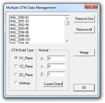
Once you are happy, the DTMs can be merged into a single DTM using the “Merge” button on the “Multiple DTM Data Management” dialog:

Notice how the names of the DTMs are derived from the names of the images? Notice also how 90-92 form one model, 91-93 the next, 92-94 the third, and so on? Since these images were captured in a strip, this guarantees that at least two DTMs will cover any given point, and generally many more than two DTMs will.
Creating the template
This is all very well and good, but it does seems rather dependent on this magical “surface template” DTM, doesn’t it? Where did that come from?
Believe it or not, the DTM Filtering dialog comes to our rescue once again!
Suppose I had a collection of DTMs representing my stockpiles consisting of a few million points, and I wanted to clean up those DTMs to remove the infrastructure by hand. What’s the big obstacle to doing that?
Time.
It simply takes a really long time to edit all those DTMs because there are so many points in so many different locations that need to be deleted.
What if there was a way to dramatically reduce the number of points so that we had to delete, by hand, maybe only a dozen or so?
That’s where the “DTM Density” section of the dialog comes in. Set the density to 1 m or so, click “Reduce”, and suddenly millions of points turns into a few hundred thousand points, because any point less than the given distance from another point will be removed. (In other words, the reduced DTM is guaranteed to have no points closer together than the specified distance.)
More importantly, suddenly the points on our infrastructure start to look a lot more “spikey”. This is important, because the spike removal feature in that same dialog, which is designed to remove bad points, will now start to think that the points on the infrastructure are bad because they are isolated. (Normally it’s useless for removing points on infrastructure because there will tend to be many points close together on the infrastructure; this is because the points aren’t bad — i.e. incorrectly matched — but are merely on surfaces that are unwanted.) Therefore we can do a Spike Removal operation (preferably with the “Repeat” option checked) on our filtered DTMs and suddenly a large part of our problem disappears.
We can then remove discrepancies with smoothing, exactly as described above, and it will be much, much faster because so few points are involved.
We can then merge the DTMs, and again remove spikes, and even more infrastructure will be removed. (You can also filter the DTM density again because the overlap areas between DTMs will now have a higher density.)
And, finally, we can edit the merged DTM by hand to clean up anything that was left behind. That’s how the low-resolution “template” DTM was created, shown near the top of this post. All up it should take only take a few minutes.
The larger you set the density value to, the quicker the process becomes. I used 1 m in my example above, but you could use 2 m or some other value if you prefer. In fact, after I’ve created the template and before I’ve used it to process my real DTMs, one of the first things I do is reduce the density of my real DTMs to 0.25 m or 0.5 m because for stockpile volume purposes, even that density is overkill. (In fact, for stockpile volumes, you can actually just use the so-called “template DTM” if you want!)
Of course, if you lower the density too much, you will need to be more generous in your distance setting when using the template to filter your original DTMs, because the lower density DTM won’t capture the peaks and troughs as well and points on the ground can legitimately be further away from the template DTM, which also increases the risk that you might not be able to filter out the infrastructure as easily.
Conclusion
The DTM Filtering dialog contains some simple but powerful tools, that become even more powerful when used in combination. The Spikes section normally allows you to remove bad DTM points but can, with judicious use of the DTM Density setting, also filter out a lot of the infrastructure as well. The DTM Density section likewise can have a big impact on the amount of time and effort required to process some data. The Large Triangle hiding section allows you to eliminate triangles that are likely to be suspect. And, finally, the Discrepancies section can filter DTMs with respect to a reference DTM, can remove the discrepencies between overlapping DTMs, and remove points that lie outside the footprint of a reference DTM.
One more button worth playing with is the “Smooth DTM” button, especially when creating the template. It can be pressed multiple times, each time making the DTM smoother — just don’t press it so many times that the surface loses all detail!
Pingback: Aerial Mapping with UAVs and 3DM Analyst Mine Mapping Suite « ADAM Technology Team Blog