In Part 1 I looked at the levels of accuracy and detail that customers have been able to achieve with our software.
In Part 2 I’ll show how you can estimate the accuracy beforehand so you can achieve the required accuracy with the least effort.
Estimating accuracy
You can achieve almost any accuracy required by using an appropriate pixel size on the surface. However, using smaller pixels to cover a given surface area means more pixels in total, and therefore more images to capture and more time to process them.
It is therefore important to be able to estimate the accuracy that will ultimately be achieved so that you can avoid spending more time and effort than is actually necessary for the task at hand.
As mentioned before, the size of a pixel on the surface of the area that you are trying to model is critically important so we need to calculate what pixel size we are going to get with a given camera and lens at a given working distance:
![]()
Compare the scale of the image and the scale of the object: the ratio between them is the same as the ratio between the distance d and the focal length f. Therefore, the ratio between the size of a pixel on the image sensor and the size of a pixel on the object is also the same ratio.
Expressed mathematically, we get:
pixelsizeground = (d ÷ f) × pixelsizeimage
(Note that d and f must be in the same units and pixelsizeground and pixelsizeimage must also be in the same units.)
As a real-world example, the Canon EOS 5D Mark II digital SLR has pixels of 6.41 × 6.41 µm, or 0.00000641 metres. When paired with a 100 mm lens from a distance of 200 m, the ground pixel size will be:
pixelsizeground = (200 ÷ 0.1) × 0.00000641 = 0.0128 m
or about 13 mm (about half an inch). (Since the pixels are square the ground pixels will also be square so the result is the same for width and height.)
How do we find out what the image pixel size is? Sometimes this is published by the manufacturer, but more usually we simply find out what the size of the sensor is, and divide it by the maximum resolution of the camera. For the 5D Mark II, for example, the image sensor is 36 mm × 24 mm, and the maximum resolution is 5616 × 3744 pixels, so the horizontal pixel size is 36 mm ÷ 5616 pixels = 0.00641 mm = 0.00000641 m. Do the same calculation with the height and we get the same answer, so the pixels in this case are square, which is fairly common. (Note that it doesn’t matter if the numbers are a bit off — the software will detect this during the calibration process and compensate for it.)
OK, so now we know how big a pixel is on the object’s surface/ground. How do we work out the accuracy?
Suppose that we knew the accuracy in terms of pixels in the image sensor, σpixel. Using the above formula, we could easily convert that into ground units by multiplying it by the ground pixel size:
σplan = σpixel × pixelsizeground
So if the accuracy in terms of pixels is, say, 1/3rd of a pixel, and the ground pixel size is 3 cm, then the accuracy on the ground is 1 cm.
But that’s only in a particular plane — that’s what the “plan” subscript is for. This is the accuracy in the plane that is parallel to the image sensor in the camera, known as the planimetric accuracy. (The word “plan” arises from the fact that photogrammetry has long been used for aerial mapping using images captured from aircraft with the camera looking straight down; in that situation the image sensor is parallel to the ground — i.e. the plan view.)
Since the image sensor is two-dimensional, the plane parallel to it is two-dimensional as well, and each dimension on that plane has the accuracy described above. But there is a third dimension, and that’s the one parallel to the view direction — the “depth” (or “height”, for aerial photography) accuracy.
To calculate the depth accuracy we also need to know how far the cameras are apart — in fact, the ratio between camera separation (b for base) and distance:
σdepth = (d ÷ b) × σplan
So, if we had two images captured by a Canon EOS 5D Mark II with a 100 mm lens captured from 200 m away and taken 50 m apart, and our image accuracy was 1/3rd of a pixel, we would expect to have:
-
A ground pixel size of 12.8 mm;
-
A planimetric accuracy of 1/3 × 12.8 = 4.3 mm; and
-
A depth accuracy of (200 ÷ 50) × 4.3 = 17 mm.
The next obvious question is “How do we know what the image accuracy should be?”. This one is a bit harder to answer because it depends on a few factors, like the quality of the images (noise and blur) and the accuracy of the camera calibration. In general, however, it is fairly safe to plan a project on the assumption that you will achieve an image accuracy of 0.5 pixels, and expect to get about 0.3 pixels. The exception is in cases where image quality is likely to be worse than normal (e.g. subsea imagery) in which case you might plan a project assuming about 1 pixel accuracy.
The best accuracy we have actually achieved, using circular targets, is 0.05 pixels, and the best accuracy we have achieved using natural points is about 0.15 pixels.
Visualising Accuracy
It is worth taking a moment to try to understand why the accuracy behaves like it does.
Firstly, what do we mean by “image accuracy”? This can be described as “uncertainty in the precise location of a point in an image”. This uncertainty has multiple causes, but for now it’s sufficient to acknowledge that we don’t know exactly where a point is in an image to infinite accuracy, and so therefore we must associate an error interval with each point’s location.
This uncertainty in the point’s location translates into an uncertainty in the direction of the ray that we project from that point, through the perspective centre, into the scene.
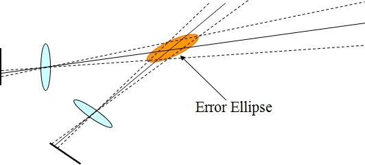
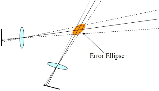
In the image below, for example, I have drawn dashed lines illustrating the range of possible ray directions associated with the range of possible locations within each image for each point, and illustrated the possible intersection locations in the real world with an “error ellipse” (because the shape of possible intersection locations is roughly elliptical):

In that image, “planimetric accuracy” is uncertainty in the plane that cuts the ellipse at right angles to the view direction, and “depth accuracy” is uncertainty in the long axis of the ellipse.
(If you’ve been paying attention you may have noticed that there are actually two planes formed by the two image sensors, and they aren’t parallel to each other. In fact, the formulas above are only true when the cameras are parallel to each other, looking in the same direction. Rotating the cameras with respect to each other causes a slight change in the formulas, but the difference is small as long as the angles aren’t too great that we can ignore that and keep the formulas simple.)
Now, if we move the cameras further apart — increasing the base:distance ratio — it’s immediately apparent why increasing the camera separation improves the distance accuracy: the ellipse becomes more circular.

Conversely, if we move the cameras closer and closer together, the ellipse becomes more and more elongated, until it stretches to infinity at the point where the two cameras co-incide and we are in the same situation we would be in with just one image — no depth information at all. In the depth accuracy calculation above, this co-incides with the divisor b becoming zero, which means the value of (d ÷ b) goes to infinity.
So, estimating the accuracy of the data beforehand is actually quite easy. The next question is: how much effort is required to achieve a given level of accuracy? In Part 3 of this series I’ll present a number of case studies of real-world projects to show the time and effort required to achieve the desired outcomes.