This system was developed for a Garbage incinerator plant. It monitors the fill level of the main bunker and the hoppers. It is designed to interface into a system that automatically controls the cranes and the fire-fighting equipment.
Bunker fill level monitoring system
The trucks dump the garbage into the main pit (bunker), which measures approximately 40 x 20 x 20 meters. The cranes lift the refuse from the main pit
into one of the four hoppers. These cranes are operated automatically using the data fed back from the CCD cameras to the control system. From the hoppers the refuse is fed into the furnaces, where it is burnt. It is important that proper fill levels are
maintained in the hoppers to ensure optimal incineration, hence the importance of the automatic operation. |
Hopper measurement system
| The hopper system utilises two CCD cameras to acquire stereo images over the hopper area. A DTM and volume of material in the hopper are computed from the 2 images. The resulting volumes are sent to the control system. A single PC can monitor up to four hoppers. |  Figure 2. Image of hopper with DTM |
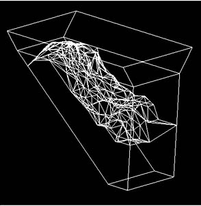
Figure 3. Wire frame display of hopper and DTM