ADAM Technology's analytical stereoplotters and conversions are used all over the world by mapping organisations and government departments. The ADAM PROMAP, first introduced 32 years ago, was well regarded for its accuracy, reliability, and ability to scan and orthorectify images with the optional ADAM ORTHO System upgrade.
3DM Analyst Professional has been designed to be the logical successor to these outstanding instruments. Able to support images in excess of 250 megapixels (230 mm images scanned at 15 microns), 3DM Analyst Professional allows mapping organisations to boost productivity with features like fully automatic DTM generation and, when combined with 3DM CalibCam, automatic relative-only point generation for aerial triangulation.
3DM Analyst Professional can also use images from digital cameras directly, ranging from $100 consumer digital cameras all the way up to large format digital cameras.
Apart from supporting large format images, all of the features of 3DM Analyst Professional are also present in the standard version of 3DM Analyst, allowing 3DM Analyst to be used as a professional mapping tool in situations where large format images are not required.
Manual Digising
While the automatic features like DTM and contour generation are important in mapping, most of the time spent during mapping will be spent manually digitising vector data, so it is important that a professional mapping tool has outstanding capabilities in this area.
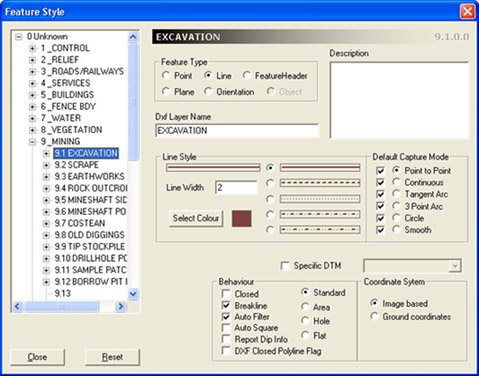
The software allows up to 160,000 user-defined feature types to be specified in a hierarchy of four levels with 20 feature types per level. Each feature type can be assigned a DXF layer name for importing from and exporting to DXF. Features can be points or lines, among others, and line features can be captured in point-to-point mode, continuous mode (points are added to the line continuously as the floating mark is moved, recording every movement the operator makes), two different arc modes (for curbs, etc.), circle mode, and smooth mode (like point-to-point mode except the points are connected by smooth arcs). The user can switch between modes at any time while digitising a line.
Line features can also affect the DTM:
Breaklines allow the user to specify that triangles should not cross a certain feature;
Areas allow the user to specify where DTM points should be automatically generated;
Holes allow the user to specify where DTM points should not be generated, leaving a hole in the DTM; and
Flats allow the user to specify that there should be no points within an area but the area itself should remain part of the surface (good for buildings, allowing contours to be generated through buildings as if they weren't there).
Areas, holes, and flats can be nested and the system will honour them all (e.g. the user could specify a hole or a flat line feature around a lake, but an area line feature around an island within the lake).
Lines can also be automatically squared (the software will make nearly parallel lines parallel and nearly perpendicular lines perpendicular if it can do so without moving any point by more than the amount you have specified in the job's accuracy setting — also good for digitising buildings) and closed. Dip and dip direction can also be reported if desired.
Data can be digitised in full colour stereo using either a StereoGraphics Z-Screen with polarising glasses or LCD shutter glasses, or in anaglyph mode. It can also be digitised in the 3D View directly onto the automatically-generated terrain surface, or in the Images View in Single Image Digitising mode (where the software automatically locates the corresponding point in the other image, first by using the DTM then fine-tuning it by performing image matching).
The software naturally also supports our full range of handwheels, footdisks, and footswitches as well.