A question that occasionally comes up is whether texture is really required in order to successfully map structures. (This question is normally asked in connection with the use of laser scanners (LIDAR) that generate a point cloud rather than a textured 3D surface model. For the purpose of this Blog post I’m going to assume that the quality of the surface data isn’t an issue, i.e. the laser scanner is capable of producing a surface model that is detailed and accurate enough, and that the only question is whether adding texture has any value.)
The answer is “It Depends”.
If all the structures that need to be mapped are easily visible in the point cloud then a simple surface model may be enough.
The problem is that, in general, not all structures are visible in the point cloud/surface model.
To illustrate the point, I have uploaded a video to our YouTube channel. (If you have a good Internet connection and a Full HD monitor then click on the little Settings icon at the bottom-right of the video (![]() ) and select 1080p60HD to watch it at full resolution. If it gets jerky or stutters then try 720p60HD. Unfortunately if you need to lower the resolution more than that then you might find it hard to read the text.)
) and select 1080p60HD to watch it at full resolution. If it gets jerky or stutters then try 720p60HD. Unfortunately if you need to lower the resolution more than that then you might find it hard to read the text.)
The project is question is one of our training projects of a road cut near Vancouver:
The average ground pixel size is about 2.7 mm and the mean point spacing is 17 mm. Images were captured from the south side of the road, 25-30 m away from the rock face, with a Canon 5D and a 100 mm lens.
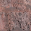
In the image below we have a small portion of the rock face (about 1.5 m × 1.5 m) from that video that happens to be a nice example:
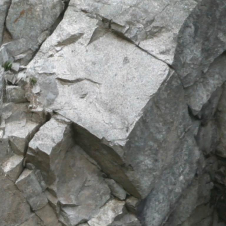
Without texture it looks like this:
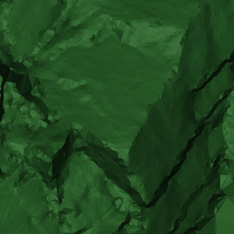
Even without texture we can easily pick up faces:
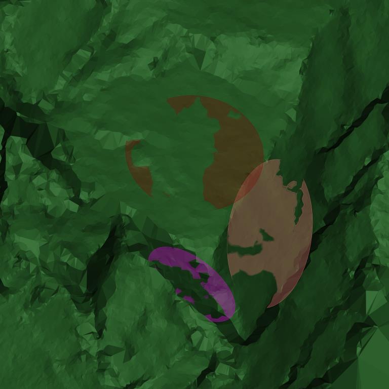
But note the fourth feature (uppermost, in purple below); it is easily seen and therefore can be easily digitised when the texture is draped over the surface (see the first image to see how it looked originally) but it is almost completely invisible in the screenshots without texture, and certainly its extent is not apparent:
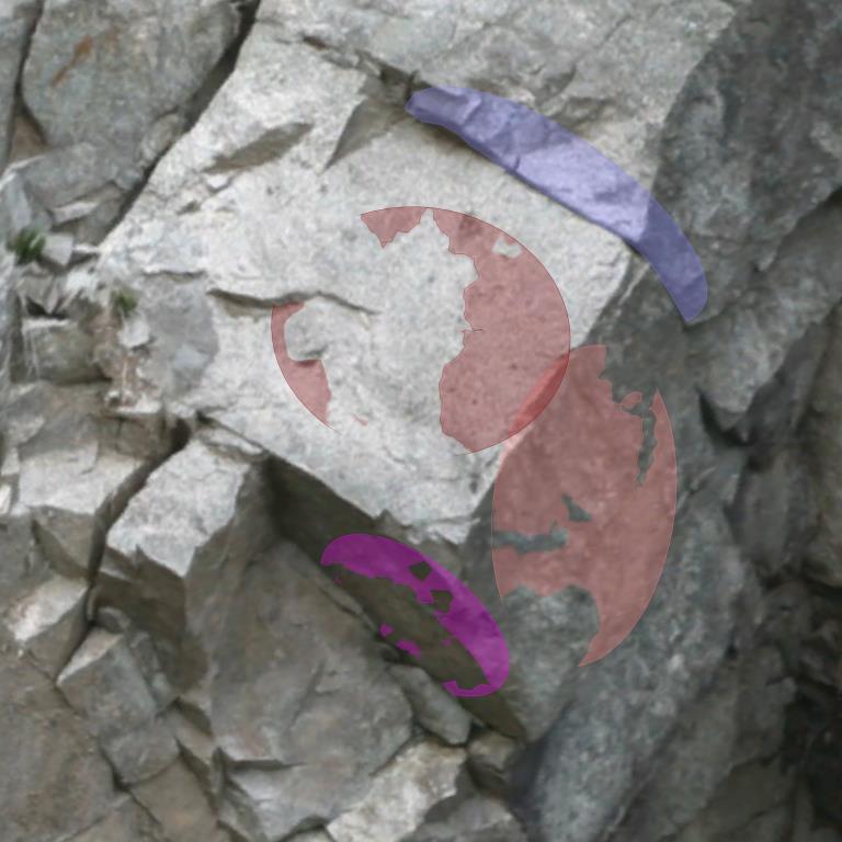
In general, without texture, it is not possible to pick up features that do not cause a change in the surface — if the rock to the left and right of the feature is at the same level for most of its length, then it simply doesn’t appear when looking at the surface model without texture. With texture, the fracture is clearly visible. (Note also that even if the fracture does appear in the surface model for part of its extent, unless you can see the full extent of the fracture — i.e., the rock has fallen away on one side the entire length of the feature — then you will tend to underestimate its persistence without the texture.)
To further illustrate the point, here’s the result of running the Automatic Face Detection operation on that project (I didn’t show it in the video) and showing all features above 0.5 m in size:
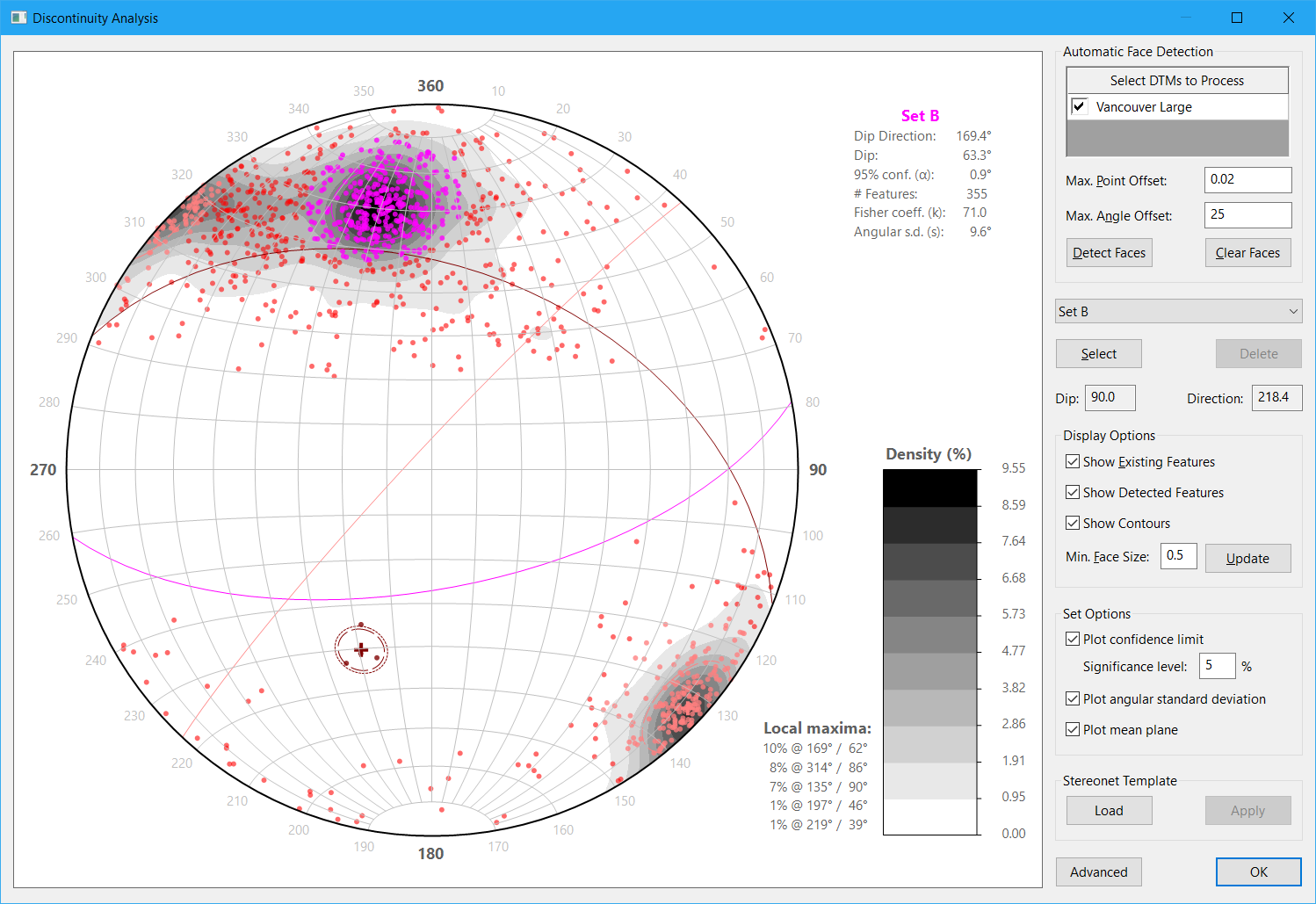
(Click for a clearer view.)
It has no trouble picking up hundreds of examples of Set B (the first and second features I digitised in the video are in this set) and Set C (the third feature I digitised is in this set) but only found four examples of Set A and all are like the fifth feature I digitised in the video in that the rock on one side had already fallen away. (In fact, that feature was one of the four it picked up automatically.) Yet that set is really easy to digitise when imagery is draped over the surface model and would be easy to map in the field as well. It just happens to manifest mostly as traces rather than faces, i.e. the rock on both sides is still intact for much of the length of the features.
Another danger with using surface models without texture (or simply using the Automatic Face Detection operation to detect faces, since it also ignores texture) is that you might not even be aware that you were missing out on entire sets of features (e.g. see the stereonet above), i.e. you didn’t know what you didn’t know. It’s always a good idea to do some field mapping just as a sanity check/ground truthing — in the above case, it would be obvious that a major set was missing from the automatically-generated data because those features are huge and readily apparent.
Can I simply drape an image over the surface model?
It’s possible to texture the surface model derived from laser scanning/LIDAR by separately taking images of the rock face and then draping them over the surface model.
This needs to be done very carefully, however, to avoid the risk of pixels being misaligned on the surface model. (This can be dangerous because if the pixels you see do not correspond to where the feature actually is relative to the mesh then you’ll be mapping on the surface in the wrong location and therefore the location and orientation will almost certainly be wrong as well.)
To do it correctly (which is how it is done in our software), you need to calibrate the camera and lens to correct for lens distortions (which can be in excess of 100 pixels if not corrected) and georeference the image properly. (Our software can import point clouds in ASCII XYZ format and create a 3D surface model from them, and it can import surface models in Wavefront OBJ, DXF, Surpac DTM, and Vulcan 00t formats.)
The problem with this approach is that the work required to do it successfully is not much less than the work required to just do everything with photogrammetry and not use the laser scanner at all. Given the additional time and cost involved with using the scanner it is probably only worthwhile in instances where you wish to use data that has already been captured by a laser scanner rather than setting out to deliberately use this workflow.
What about scanners that capture images?
There are laser scanners on the market that capture images as the same time as the point cloud, either with a built-in image sensor or by bolting on an off-the-shelf digital camera.
There are two main issues with this approach:
1. Image alignment
If the camera is not calibrated correctly — and this includes calibrating the relationship between the camera and the scanhead, which could easily get out of alignment with rough treatment (or even just thermal expansion…), the issue with misaligned pixels comes into play again, and it’s not always obvious that the apparent location of features from looking at the images does not line up with the location in the surface model. This issue does not arise with photogrammetry because the images are the source data for the 3D surface model so the two are always aligned.
2. Ground pixel size
The scanners I’m familiar with use very short focal length lenses (in the order of 20 mm), for a very simple reason — the scanners have a reasonably large vertical field-of-view, and customers would expect the scanner to be able to drape an image over the entire point cloud and not just a narrow strip in the middle. To get a wide field-of-view, you need a short focal length lens. The problem with this is it comes with a tradeoff — a wide field-of-view means a large pixel size on the ground. The size of a pixel on the ground pretty directly determines the width of the fractures that you can actually see in the image, so if your pixel size is too large, you simply won’t be able to see the features you are trying to map.
To illustrate the point, let’s look at a series of images of the same section of a pit wall captured using a Canon 5D from 550 m away, all scaled to the same size on the screen so the difference in detail can be seen clearly.
The first image was captured with a 50 mm lens:
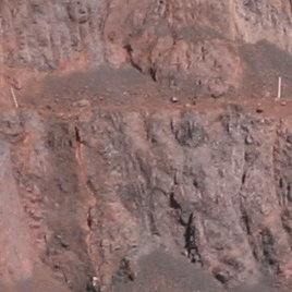
The ground pixel size in that image is approximately 90 mm.
Below is the same area captured from the same location with the same camera but with a 100 mm lens:
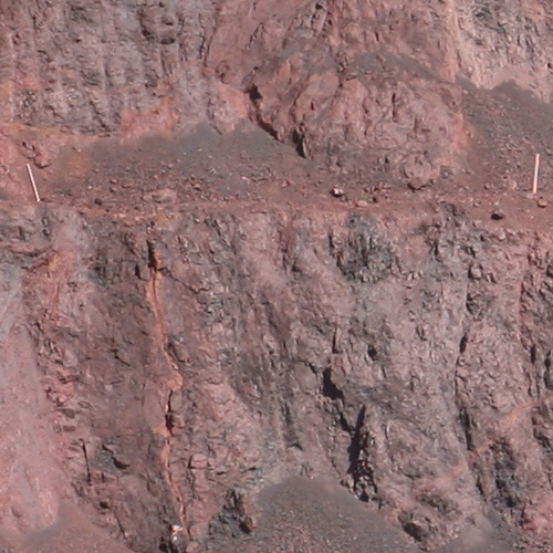
In that image the ground pixel size is 45 mm.
Finally, below is what would be considered a “normal” working image from that distance, again using the same camera from the same location but this time using a 200 mm lens to give a ground pixel size of 23 mm:
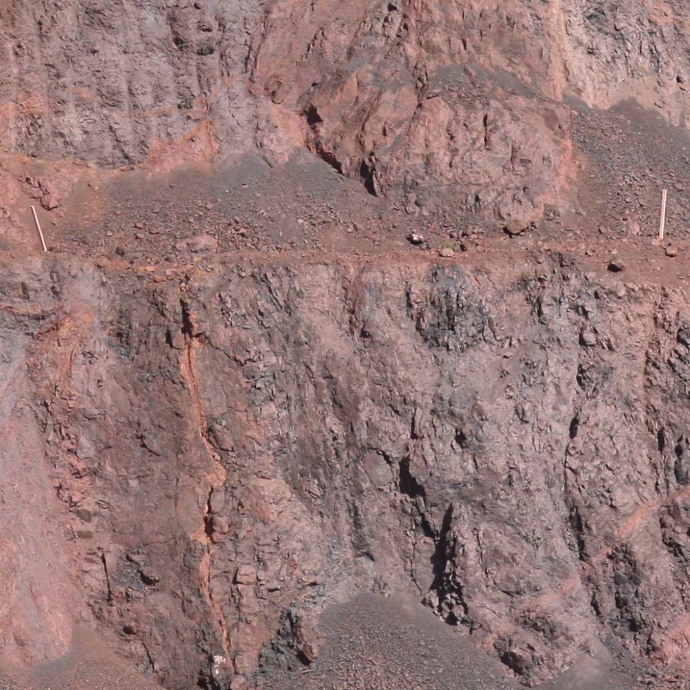
(This image actually has to be scaled down to fit so click on the image to see the original resolution.)
Compare the above to what would be seen on one of the high-end laser scanners with integrated image capturing using a 20 mm lens from the same vantage point:
Clearly, draping an image over the surface model is only part of the story. To be useful for structural mapping, the ground pixel size must also be small enough to actually see the features being mapped.